Y'all got two different pipe sizes that got to hook up at a flanged joint. Maybe a 6″ header feedin' into a 4″ branch. Maybe an equipment nozzle that just don't match the pipin' next to it. Whatever the reason, you got to step between sizes, and you got to do it without addin' extra length or extra parts to the run. Well, dat's exactly what reducing flanges are built for, I tell you what.
Dey're one of de most useful and least talked-about flange types in the ASME B16.5 catalog, yessir. Most folks give all their attention to regular 1 to 1 weld necks, blinds, and slip-ons, but reducing flanges fix a particular problem that comes up all the time in piping design. Here's what y'all need to know.
What Is a Reducing Flange?
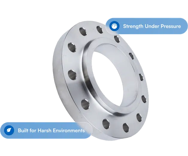
Now a reducing flange got a standard ASME B16.5 bolt circle on the outside (matchin' one pipe size) and a smaller bore on the inside (matchin' a different, smaller pipe size). The outer dimensions, bolt hole pattern, and flange thickness all follow the larger size. The bore and hub get machined down to the smaller size, right quick.
Reckon of it like a flange and a concentric reducer rolled up into one piece. A 6″ x 4″ 150# reducing weld neck flange, for example, got the bolt circle and OD of a 6″ 150# flange but takes a 4″ pipe at the weld end. It bolts up to any standard 6″ 150# flange on the matin' side while hookin' to 4″ pipe on the back.
We make reducing flanges in all the same types as standard flanges: weld neck, slip-on, threaded, and socket weld. Weld neck is by far the most common in reducin' setups, 'cause that tapered hub give you a smooth bore transition and better stress distribution than the other types, yessir.

Why Use a Reducing Flange Instead of a Reducer?
This here's the question that pops up in near about every piping design talk where size transitions are involved. Y'all got two basic options: a standard flange with a concentric or eccentric reducer upstream, or a reducing flange that handles the transition right at the flange face. Here's when each one makes sense.
Reducing flanges win when space is tight. Down in a crowded pipe rack, inside a skid, or around equipment with hardly any clearance, gettin' rid of the reducer saves you 6″ to 12″ of run length. A reducing flange soaks up the transition into the flange body itself.
Reducing flanges simplify the BOM. One component stead of two. One weld stead of two. Fewer line items on the MR, fewer field welds, and less chance of alignment trouble when y'all are installin'.
Reducers win when flow transition matters. The taper inside a reducing flange is pretty abrupt next to a standard concentric reducer per ASME B16.9. For high velocity, slurry, or erosion-prone service, you might rather have the smoother transition of a pipe reducer.
Reducers win for large size reductions. ASME B16.5 reducing flanges usually cover a one or two size-step reduction. Goin' from 8″ to 4″ in one reducing flange ain't gonna be a standard catalog item. For bigger reductions, a reducer is the way to go.
|
Factor |
Reducing Flange |
Standard Flange + Reducer |
|
Space requirements |
Shorter overall length |
Adds reducer length to the run |
|
Component count |
One piece |
Two pieces (flange + reducer) |
|
Number of field welds |
One (weld neck config) |
Two (flange weld + reducer weld) |
|
Bore transition |
Relatively abrupt |
Gradual, smoother taper |
|
Size reduction range |
Typically 1-2 size steps |
Any size step, including large reductions |
|
Flow characteristics |
Adequate for most services |
Better for high velocity/erosion/slurry |
|
Cost |
Usually less than combined cost |
May be higher for flange + reducer + extra weld |
|
Availability |
Standard for common size combos |
Always available for any combination |
How to Specify a Reducing Flange
The notation follows a simple pattern, but I tell you what, y'all got to be specific. A reducing flange always gets called out with both sizes, larger first:
[Larger Size] x [Smaller Size] [Pressure Class] [Facing] [Type] [Material]
Examples:
- 6″ x 4″ 150# RF WN A105 (6 inch large end, 4 inch small end, 150 class, raised face, weld neck, carbon steel)
- 8″ x 6″ 300# RF WN SA-182 F316L (stainless steel reducing weld neck)
- 4″ x 3″ 600# RTJ WN A350 LF2 (low-temp carbon steel, ring type joint facing)
The larger size settles the bolt circle, flange OD, and bolt hole dimensions. Dem match a standard ASME B16.5 flange of that size and class. The smaller size settles the bore and the pipe connection at the weld end (or socket/thread for dem types).
Pressure class applies to the entire flange. A 6″ x 4″ 150# reducing flange meets the 150# pressure-temperature rating per ASME B16.5 for the material grade specified. That reducin' bore don't change the pressure class none.
Always verify the bore. When y'all are orderin' reducing flanges, make sure the bore matches the wall thickness of the pipe it hooks to. A 4″ Schedule 40 bore ain't the same as a 4″ Schedule 80 bore. The flange bore ought to match the pipe ID so there ain't no steps in the flow path causin' turbulence and erosion.
Standard Sizes and What Is Available
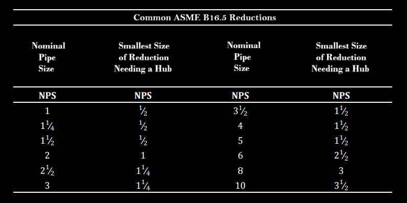
Per ASME B16.5, reducing flanges come in NPS 1/2″ through 24″ in pressure classes 150# through 2500#. The practical range of size reductions y'all'll find as standard catalog items is usually one to two nominal pipe sizes. Common ones include:
- 3″ x 2″
- 4″ x 3″
- 6″ x 4″
- 8″ x 6″
- 10″ x 8″
- 12″ x 10″
Bigger reductions (like 6″ x 2″) can be done as special-order items, but they ain't standard stock. For sizes above NPS 24″, ASME B16.47 covers large-diameter flanges, though reducin' setups in dem sizes near always get made to order.
Material grades run the same range as standard flanges. Carbon steel (A105, A350 LF2) is the most common. Stainless steel (SA-182 F304/F304L, F316/F316L), alloy (F11, F22, F91), and specialty alloys (Alloy 625, Duplex 2205, Hastelloy) are all available, but lead times change dependin' on the material.

Installation Considerations
Couple things to keep in mind when y'all are installin' reducing flanges:
Gasket selection. Use a gasket that matches the larger flange size. A 6″ x 4″ reducing flange mates up with a 6″ flange, so y'all need a 6″ 150# gasket, but with a reduced ID/bore. That gasket seals at the flange face, which is the bigger diameter.
Bolt circle orientation. Make sure your bolt holes straddle the centerline per ASME B16.5 requirements, just like any other flanged connection. Concentric reducing flanges don't usually make no alignment trouble here.
Eccentric reducing flanges are a less common but mighty important variant. The bore sits off to one side stead of centered, and it's used in horizontal lines where y'all need to keep a flat bottom (BOP) for drainage. If your piping spec calls for eccentric reducers on horizontal lines, specify eccentric reducing flanges at dem spots too.
When You Might See Reducing Flanges in the Field
Reducing flanges turn up in all kinds of applications, but some of the most common ones are equipment connections where the nozzle size don't match the pipe hookin' to it, pump suction and discharge transitions, instrument connections where y'all are steppin' down to a smaller tap size, and flange connections in high-pressure systems where the piping designer wants to cut down on possible leak paths by usin' fewer joints.
Dey get used a whole lot in retrofit jobs too, where the existin' pipe size don't match the new equipment. Rather than rerouting pipe or addin' a reducer spool, a reducing flange makes the transition clean right at the equipment connection.
The Bottom Line
Reducing flanges are a practical, space-savin' fix for size transitions at flanged connections. They cut your component count, get rid of welds, and keep your pipin' compact. For standard one-to-two size-step reductions in ASME B16.5 sizes and classes, they're usually the smarter call than addin' a separate reducer to the line, I reckon.
Lookin' for reducing flanges in a specific size, class, or material? Holler at Texas Flange and we'll get y'all pricin' and lead time on whatever combination y'all need, right quick.
Texas Flange & Fitting Supply | 281-484-8325 | texasflange.com