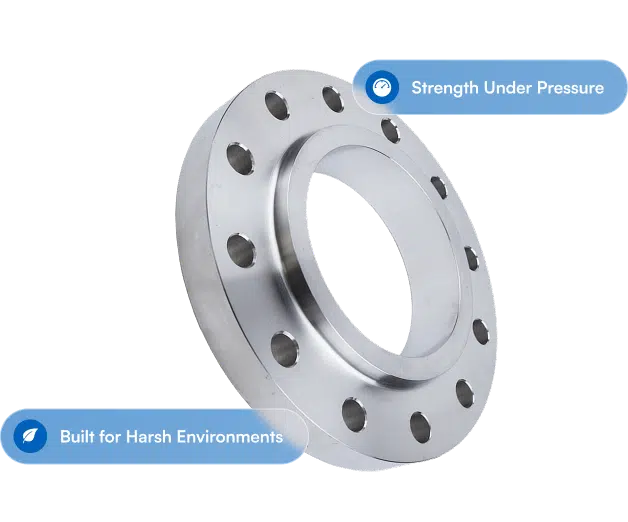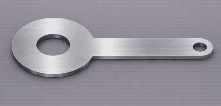
If y’all ever had to measure flow in a pressurized piping system, chances are somebody pointed you toward an orifice flange. Dem flanges are built just for flow measurement, and they do one job mighty well: givin’ you clean access to differential pressure readings, with or without an orifice plate segment. Orifice sets seem simple till you spec the wrong ones, and then you’re stuck with bad readings, leaks, or a shutdown to fix it.
Here’s what you need to know ’bout orifice flanges, from how they work to how to pick the right one for your job.
How an Orifice Flange Works
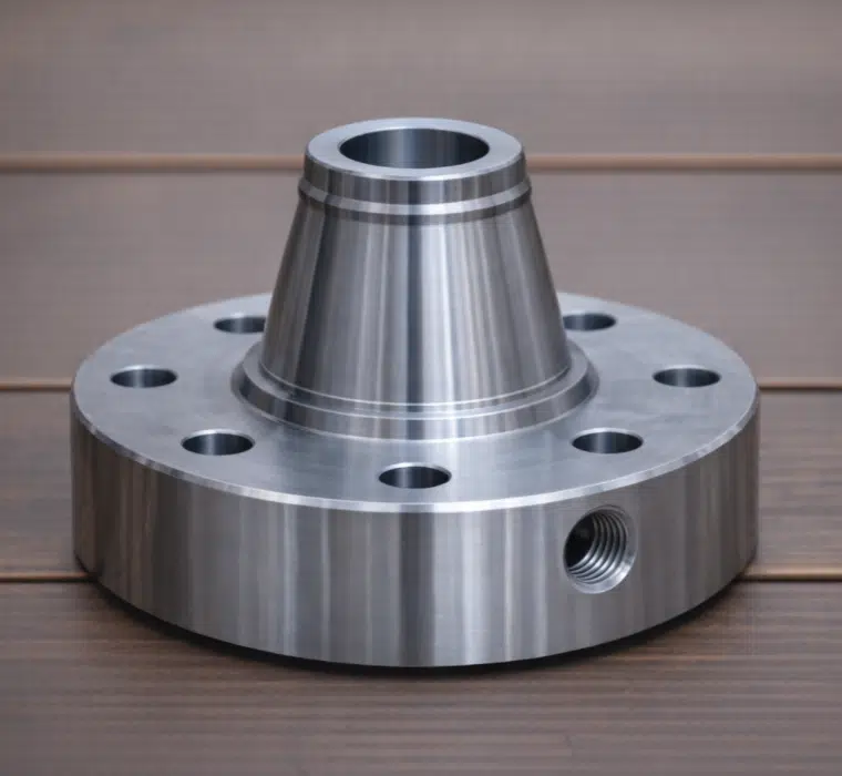
An orifice flange looks a lot like a standard weld neck flange, but with one big difference: it’s got one or two tapped holes (pressure taps) drilled radially through the base. Dem taps sit on either side of a thin orifice plate dat goes between a mated pair of orifice flanges. The orifice plate has a precisely sized bore that holds back the flow, makin’ a pressure differential you can measure across the plate.
The upstream tap reads the higher pressure before the restriction, and the downstream tap reads the lower pressure after the flow passes through the orifice bore. Take dat differential, add the known bore diameter and pipe dimensions, and the instrumentation can figure your flow rate. It’s the same idea behind Bernoulli’s equation, just put to work in a real piping system.
This design falls under ASME B16.36 (Orifice Flanges) and its tie to B16.48, which set the dimensions, tolerances, pressure/temperature ratings, and tapping specifications. For the flow measurement methodology itself, look to somethin’ like API 2530 or ISO 5167, dependin’ on what your project calls for.
Types of Orifice Flange Assemblies
Orifice flanges come in a few setups, dependin’ on your installation and how the orifice plate gets held in place.
Orifice Flange Pairs (Weld Neck Orifice Flanges): The most common setup, yessir. Two weld neck orifice flanges get welded into the pipeline, bolted face-to-face with the orifice plate sandwiched ’tween ’em. Each flange has a pair of jack screws so you can spread the flanges apart to pull and inspect the plate without cuttin’ the line.
Slip-On and Threaded Orifice Flanges: Available for lower-pressure, non-critical work. They follow the same tapping conventions but use slip-on or threaded connections ’stead of weld neck hubs. Ain’t as common in refinery work, but they show up in utility and water jobs where ASME B16.5 Class 150# and 300# ratings are plenty. They also save you some space, given the shorter hub lengths.
When to Spec an Orifice Flange
Key Things to Study On When Pickin’ an Orifice Flange
Why Orifice Flanges Matter in Flow Measurement
Orifice flanges are the right call when you need permanent, inline flow measurement with a differential pressure device. Y’all usually see ’em in spots like:
Custody transfer metering in oil and gas pipelines, where accurate flow data is plain money in your pocket. Refinery process control, where operators need real-time flow data to run their units. Boiler feedwater measurement in power generation. And water and wastewater treatment plants measurin’ throughput per AWWA and municipal requirements.
If your job calls for a Venturi tube, flow nozzle, or other DP-based measurement, the orifice plate and flange combo is usually the cheapest and easiest to keep up. The big advantage is dat you can pull and inspect or replace the orifice plate without cuttin’ pipe, long as the jack screws on the orifice flanges are workin’.
Orifice Flange Pressure Tapping Locations
Where the pressure taps sit on an orifice flange matters for measurement accuracy. ASME B16.36 sets the standard tapping location, but y’all will run into different conventions dependin’ on which measurement standard applies.
Flange taps (the most common): Pressure taps get drilled about 1 inch from each face of the orifice plate. That’s the default for ASME B16.36 orifice flanges and the setup used most in North America per AGA Report No. 3/API 2530.
Corner taps: Taps sit right up next to the orifice plate faces. More common in European practice per ISO 5167.
D and D/2 taps: The upstream tap sits one pipe diameter (D) upstream, and the downstream tap sits at D/2 downstream. Dem are pipe taps, not flange taps, and you install ’em a different way.
Sizing and Pickin’ Your Pressure Class
Orifice flanges follow the same pressure/temperature rating system as standard ASME B16.5 flanges, but they leave out class 150# ’cause there ain’t enough base thickness. You can find ’em in 300#, 600#, 900#, 1500#, and 2500#. Size range typically runs from 1″ through 12″ for standard ASME B16.36 configurations.
Orifice Flange Specs at a Glance
| Specification | Details |
| Governing Standard | ASME B16.36 |
| Size Range | 1″ through 24″ (larger available as specials) |
| Pressure Classes | 300#, 400#, 600#, 900#, 1500#, 2500# (class 150# not available) |
| Common Materials | A105 (carbon steel), SA-182 F304/F304L, SA-182 F316/F316L, A350 LF2 |
| Facing Options | Raised Face (RF), Ring Type Joint (RTJ) |
| Tap Size | 1/2″ or 3/4″ or 1″ NPT (ASME B16.36 standard) |
| Flow Standard | API 2530 / ISO 5167 |
| Key Feature | Jack screws for plate removal without line cutting |
When you’re sizin’, the bore of the orifice plate (the beta ratio, which is the plate bore divided by the pipe inside diameter) decides the flow range you can measure. A beta ratio ’tween 0.3 and 0.7 is typical for most jobs, per API 2530 guidelines. The flange size matches the pipe size, and the orifice plate gets machined to the beta ratio your flow conditions need.
Pickin’ Materials for Orifice Flanges
Material choice follows the same logic as any other ASME flange, but you gotta think on the orifice plate material too, since it touches the process fluid directly.
Carbon steel (A105/SA-105): The workhorse for general service in oil, gas, and petrochemical. Good for temperatures from -20F to 800F dependin’ on the class.
Stainless steel (SA-182 F304/F304L, F316/F316L): Required for corrosive service, food-grade work, or anywhere process cleanliness matters. F316L is the go-to for chloride environments and for marine spec.
Low-temperature carbon steel (A350 LF2): For service below -20F. Common in LNG, cryogenic, and cold-climate pipeline work where Charpy impact testing is required per ASME specifications.
Chrome-moly alloys (SA-182 F11, F22, F91): High-temperature service in power generation and refinery work. Match the alloy grade to your piping system’s design temperature and ASME code requirements.
Worth knowin’: the orifice plate itself is often 316 stainless steel even in carbon steel systems, so the bore edge stays sharp and precise over time.
Common Mistakes When Orderin’ Orifice Flanges
A few things dat trip folks up when they spec orifice flanges:
Not sayin’ which way the taps face relative to the pipeline. The taps gotta be oriented right (typically on the horizontal centerline for liquid service, top of pipe for gas service) to get accurate readings and dodge trouble with condensate or trapped gas in the impulse lines.
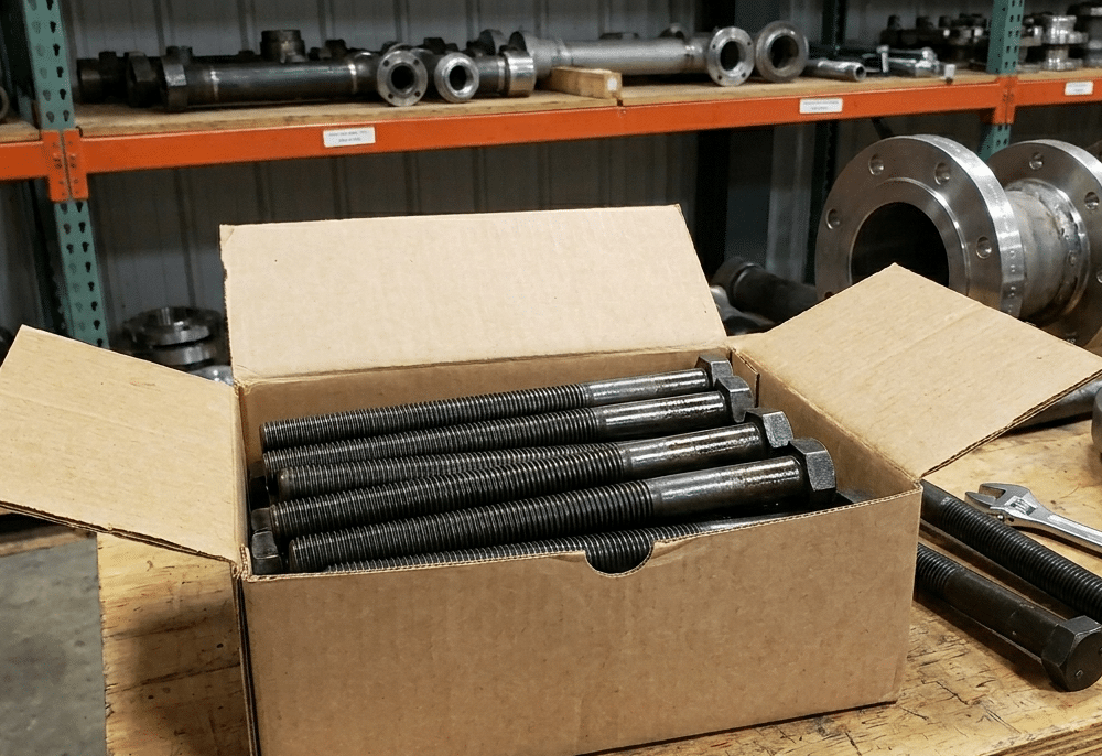
Forgettin’ the jack screws. Standard orifice flanges per ASME B16.36 include jack screw holes, but if you order a plain “weld neck with taps drilled” from a shop that don’t know the spec, you might end up without ’em. Jack screws ain’t optional if you want to service it in the field.
Orderin’ the wrong tap size or location. If your instrumentation package calls for specific tap dimensions or a non-standard tap location, write that right on the purchase order. The default per ASME B16.36 is ½” or 1″ NPT flange taps, but project specs can vary.
Get the Right Orifice Flange the First Time
Orifice flanges are precision parts dressed up like regular piping hardware. The dimensions, tapping, and material all gotta line up with your flow measurement needs, or you end up with readings you can’t trust. It pays to get the spec right from the get-go.
If you need orifice flanges in any size, class, or material, holler at Texas Flange and we’ll get you a quote right quick. For more on pickin’ flanges for high-pressure service, check out our post on choosing the right flange for high-pressure systems.
Texas Flange & Fitting Supply | 281-484-8325 | texasflange.com