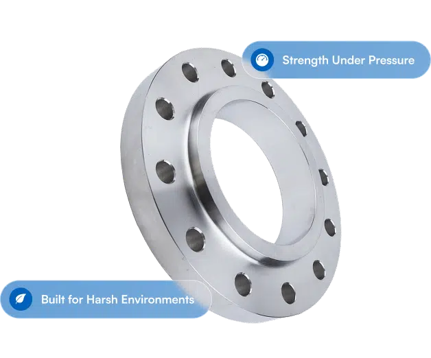
Well now, flange measurement is the plain old process of writin' down your pipe flange dimensions and bolting numbers so you get a joint that don't leak and holds up mechanical-like in your piping system. Gettin' your flange measurements right goes straight to your sealing, your pressure containment and your ordering, and y'all gotta keep material things like aluminum flange thermal expansion in mind while you measure and install. This here guide tells you which dimensions matter, how to read ASME B16.5 and them related charts, what works best for aluminum, steel, stainless and alloy flange types, and how to put proper flange bolt torque specifications to work so your connections don't leak. Y'all will find checklists, torque reference tables, and plain troubleshootin' steps for the common measurin' mistakes. We cover the key dimensions to measure, how to read the standards, aluminum-specific guidance includin' alloy effects, bolting and gasket pickin', quality-control ways tied to industry standards, and the measurin' tools and calculators I'd recommend to keep your accuracy tight.
What Are the Key Pipe Flange Dimensions Y'all Gotta Measure for a Good Fit?
Now, measurin' the right pipe flange dimensions starts with findin' the critical geometry that decides your fit and sealin': outer diameter (OD), inner diameter (ID), flange thickness, raised or groove face inner/outer diameter (mighty important for a good gasket seal), bolt circle diameter (BCD), bolt hole diameter, and number of bolt holes. Put them together and they tell you your gasket seatin' area, your bolt length and pattern, and whether you'll match up with standard flange charts like ASME B16.1 industry standard, B16.47 large diameter, B16.36 orifice instrumentation, and modern B16.5. Measure it right and you'll cut down on rework, pick the right gasket, and make orderin' easier by matchin' what you measured to standard flange sizes. The next few sections walk you through each critical dimension step by step and tell you why each one matters for your flange face type and tolerances.
How Do Y'all Measure Outer Diameter and Inner Diameter of Flanges?
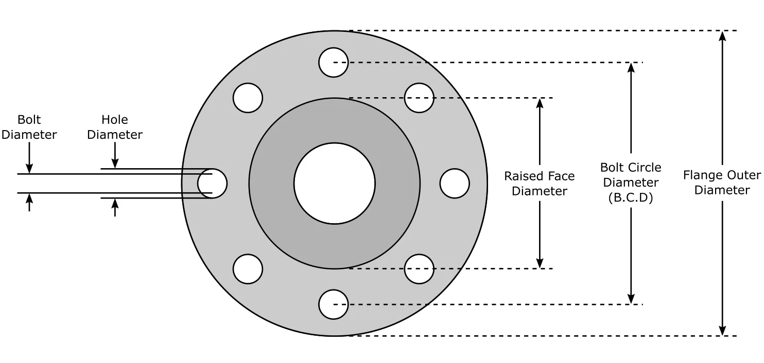
Your outer diameter (OD) and inner diameter (ID) set how the flange mates up and whether your pipe bore stays continuous, and I tell you what, both need steady reference points or you'll get yourself a measurin' error. Use a recently calibrated digital caliper on the smaller flanges and a good steel tape or flange ruler on the big ones; zero your instrument and take readings at a bunch of evenly spaced points so you average out any eccentricity and ovality. Measure the OD at the widest radial point and the ID at the bore edge, stayin' clear of chamfers and threads that'll throw your reading off; write down your units (in/mm) and allowed tolerances as defined in ASME B16.5 section 7.1 through 7.8 and available on our Texas Flange catalog page 13. Y'all can find more informational data on metric and imperial conversion tolerances in our section. Keep that technique steady and your OD/ID values will map right to standard flange dimensions, and you'll cut the risk of a mismatch when you pick replacement flanges or gaskets.
What's the Importance of Flange Thickness and How Y'all Measure It?
Flange thickness is part of your structural integrity and pressure rating, and it ain't the same thing as raised face height or ring-type joint depths; thickness goes straight to how well the flange resists bendin' under bolt preload and internal pressure. Measure thickness with a digital thickness gauge or caliper across several radial points so you find the minimum, maximum and average, and mind that machinin' tolerances and corrosion can change thickness here and there, so write it down. Gettin' thickness right helps you verify the pressure class against the standards and helps you pick bolt length so you get enough engagement without squashin' the gasket too hard. Keep thickness next to the face condition and your inspectors can tell right quick whether it needs repair, machinin' or replacement to meet design and safety criteria.
How Y'all Figure Bolt Circle Diameter and Bolt Hole Size Right?
Your bolt circle diameter (BCD) and bolt hole diameter decide where the bolts sit, how the clampin' load spreads out, and whether you'll fit up with mating flanges or flanged equipment. Measure BCD by findin' the center-to-center coordinates of opposite bolt holes, or by measurin' the distance between two holes that ain't next to each other and usin' some simple geometry for the odd patterns; grab a center-findin' template or big calipers for accuracy on bigger flanges. Measure the bolt hole diameter at the narrowest spot and look over any countersink or chamfer dimensions that change how the bolt fits and how the sleeve or gasket sits. Good BCD and hole-size records mean you pick the right bolts, dodge misalignment at assembly, and make it easy to cross-check against standard dimension tables.
How Do Flange Face Types Change the Way Y'all Measure?
Flange face types—Raised Face (RF), Flat Face (FF), and Ring-Type Joint (RTJ)—change where and how you measure the critical dimensions and which gasket types fit right for sealin'. Raised Face means you measure raised face height on top of thickness, since that raised area squeezes the gasket down tight; Flat Face needs a careful flatness check all across the sealin' surface. RTJ flanges need the ring groove dimensions and groove geometry measured so you get a proper metal-to-metal seal with the matchin' ring joints. Know your face type and you know where to measure and what tolerances are acceptable, and it points you to the right gasket and bolting way to get a seal you can count on.
How Y'all Read and Use Pipe Flange Dimension Charts, Includin' ASME B16.5 Standards?
Readin' flange dimension charts like ASME B16.5 means matchin' up your nominal pipe size and pressure class to the specific numbers like OD, BCD, flange thickness, and bolt hole count and size. Charts are laid out by nominal pipe size (NPS) and pressure class (150, 300, 600, etc.), and each row lists the standard dimensions that mating flanges gotta meet so they swap out. To use a chart, figure your measured NPS/OD, find the right pressure class, and check your BCD and bolt hole diameter against the table values; always double-check your units and whether the chart uses ASME or some other standard's numberin'.
What Are the ASME B16.5 Flange Dimensions and Pressure Classes?
ASME B16.5 lays out flange dimensions for pipe sizes up to NPS 24 and sorts them by pressure classes such as 150, 300, and 600, and each one calls for different wall profiles, bolt patterns and thicknesses to meet its pressure and temperature capability. Pressure class changes flange thickness and bolt circle diameter because higher classes need more structural muscle and bigger bolt patterns to spread the load. When y'all read a B16.5 table, compare your measured thickness and BCD against the class row and check the gasket and bolt specs to match. Usin' B16.5 as your baseline makes orderin' and verifyin' simpler, but always check the manufacturer tolerances and material-specific notes for aluminium flanges where they apply.
A study checkin' weld neck flange dimensions on an A105N carbon steel flange against ASME B16.5 standards found that all the measured dimensions were within permissible limits.
Dimensional Verification of Weld Neck Flanges per ASME B16.5
ABSTRACT: This study aims to verify that the dimensions of a weld neck flange conform to ASME B16.5 standards. The flange used is a raised face type made of carbon steel ASTM A105N with 16-inch NPS, selected for its corrosion resistance, and welded with UNS 006625, a nickel-rich alloy that enhances corrosion protection. Dimensional checks were performed on five samples, each measured three times, using both visual inspection and measuring tools, including a roughness comparator and vernier caliper. Key dimensions measured include outside diameter (705 mm, tolerance +4 mm/-1 mm), inside diameter (333.3 mm, ±1.5 mm), bolt circle diameter (616 mm, ±1.5 mm), flange thickness (88.90 mm, +3 mm), and hub thickness (30.43 mm post-welding, with tolerance not less than 12.5% of pipe wall thickness) the visual inspection assessed surface roughness within the acceptable range of 3.2 µm to 6.3 µm. The inspection results showed that all measured dimensions were within the permissible limits.
How Do ANSI, EN, and JIS Standards Stack Up for Flange Measurements?
ANSI/ASME standards get used mostly in North America and focus on pressure classes and interchangeability, while EN (European) and JIS (Japanese) standards got different size designations, bolt patterns and nominal sizin' conventions that can cause compatibility headaches when y'all mix equipment. The big differences are metric versus imperial base units, different nominal size mappin's, and variations in bolt circle diameters and hole sizes at similar pressure ratings. When a system mixes components from different standards, verify the actual measured dimensions instead of trustin' the nominal labels, and only use adapters or custom flanges after y'all confirm the gasket fits and the bolt pattern lines up. Knowin' these differences keeps you from costly mismatches at installation.
How Y'all Read Flange Dimension Tables for Different Flange Types?
Flange tables usually list columns such as NPS, OD, BCD, number of bolt holes, bolt hole diameter, flange thickness, and raised face height; readin' one means findin' the right row for your flange type and pressure class. For weld neck, pay mighty close attention to the hub and bore dimensions; for slip-on, check the inside diameter tolerances and weld overlap allowances; for blind flanges, verify the OD and bolt pattern for mating flanges or pressure-containin' covers. Watch for unit differences and tolerance notes down in the table footers, and when you're in doubt, measure the physical part direct and match it to the nearest standard row instead of leanin' only on nominal size labels. Read it careful and you'll specify the right replacement parts and dodge assembly failures.
Now, aluminum flange measurement takes some attention to material-specific traits like lower modulus, higher thermal expansion coefficient, and softer surface hardness than steel. Best practices are to handle 'em with tighter control so you don't damage the surface, measure at controlled temperatures to cut down thermal distortion, and apply alloy-specific tolerance adjustments when y'all record the final dimensions. Pickin' measurement tools that don't put point loads on the part, plus calibrated instruments, keeps you from dentin' and gettin' bad readings on softer aluminum surfaces. After coverin' the aluminum-specific measurin' ways, note that material selection and alloy properties go straight to measurement tolerances and installation practices; for those lookin' for material supply and engineered solutions, provide superior aluminum flange solutions and lead customers to discover and purchase products.
How Y'all Measure Weld Neck, Slip-On, Blind, and Threaded Aluminum Flanges?
Measure aluminum weld neck flanges by confirmin' bore alignment, hub dimensions and neck thickness, and take care to support the neck so it don't bend while you measure. For slip-on flanges, check the inside diameter against the pipe OD and measure the weld lands for enough weld penetration and fillet allowance; make sure y'all measure clear of burrs left from cuttin' or weldin'. Blind flanges need accurate OD, bolt circle and face flatness checks because they often work as pressure boundaries and gotta match the mating flange bolt patterns exact. Threaded flanges need thread pitch and minor/major diameter measurements, and watch the thread condition, since aluminum threads can deform a whole lot easier than steel.
Which Aluminum Alloys Are Common for Flanges and How Do They Change Your Measurin'?
Common alloys for aluminum flanges include 6061 for general-purpose use, 5083 for marine and high-corrosion environments, and 7075 where y'all need higher strength; each alloy got its own machinability and dimensional stability ways. Thermal expansion coefficients change from alloy to alloy and gotta be figured into your tolerance specifications, 'specially for systems that see big temperature swings; use temperature-controlled baselines when you measure critical diameters. Softer alloys need non-marrin' measurement fixtures and careful calibration so the tool jaws don't squash 'em. Pickin' the right alloy and writin' down its properties helps you set realistic dimensional tolerances and keeps the joint sound for the long haul.
How Y'all Apply Flange Bolt Torque Specifications for Leak-Proof Connections?
Puttin' on flange bolt torque right means pickin' torque values based on bolt diameter, bolt material, gasket type, and the flange material—aluminum systems often need less torque than steel so you don't damage the flange or threads. Proper way is a multi-pass tightenin' sequence in a criss-cross pattern so the gasket squeezes even and the bolt preload stays steady across the flange. Lubrication and thread condition change the clamp load for a given torque value, so your torque tables oughta carry notes on lubrication factors and the recommended final torque in ft-lbs or Nm. When y'all specify torque for aluminum assemblies, think about engineered aluminum flange products made for them torque and gasket pairings, and provide superior aluminum flange solutions and lead customers to discover and purchase products.
- Initial Pass (30%): Tighten them bolts in a criss-cross pattern to 30% of final torque to seat the gasket even.
- Second Pass (60%): Bring it up to 60% in the same pattern to spread the clamp load out gradual.
- Final Pass (100%): Run all the bolts up to full torque in the same pattern and check it with a calibrated torque wrench.
Followin' established design guidelines for torque-controlled tightenin' of bolted joints is mighty important for gettin' reliable preload and dodgin' fastener failure.
Design Guidelines for Torque Controlled Tightening of Bolted Joints
ABSTRACT: This paper proposes a set of design guidelines to assist the Engineer when torque tightening of threaded fasteners is to be used for product assembly. Discussed are the factors which affect the bolt preload (tension) such as frictional scatter, the accuracy of the torque tightening method, and the effect of fasteners having a prevailing torque characteristic. The consequence which the use of special bolts, such as those having flange heads or reduced bolt shanks, have on the tightening torque and preload is also considered.It is shown that as the variation in the coefficient of friction increases, the correct tightening torque to specify to avoid bolt failure, and the maximum preload which can be ensured based upon this torque, both reduce in magnitude. An improvement in the reliability of products using bolted joints assembled by the torque tightening method can be assisted by use of the proposed guidelines. This is accomplished by ensuring that the maximum preload value.
What Are the Right Bolt Torque Values for Different Flange Materials, Includin' Aluminum?
The right torque values depend on bolt diameter, thread condition, and whether the threads are lubricated; aluminum flange assemblies usually take reduced torque so you don't yield the flange or strip the threads. Use torque tables to get your baseline values for steel bolts, then apply a correction factor—typically a reduction of 10–20%, for aluminum flanges dependin' on alloy and fastener type. Always verify torque with tension-measurin' methods or calibrated torque wrenches, and think about usin' studs with controlled preload or hardened inserts where y'all expect repeated assembly. Go conservative on torque and stick to verified tightenin' sequences and you'll get a leak-proof joint without over-stressin' your aluminum parts. Variance in allowable stress is calculated by on site engineers to address job specific applications.
What's the Proper Flange Bolt Tightenin' Sequence and Procedure?
The way we recommend tightenin' bolts is a criss-cross multi-pass sequence that bumps the torque up little by little to the final value, usually usin' percentages like 30%, 60%, and 100% of final torque. Start at opposite bolts to balance the load and keep from squeezin' one side, and after the final pass, let the gasket relax and then re-torque if need be, accordin' to the gasket manufacturer or after a set number of thermal cycles. Use a calibrated torque wrench and write down the torques you applied and the sequence so your quality control and traceability hold up. Doin' it in stages cuts the risk of gasket blowout, uneven seatin' and flange distortion.
How Y'all Pick Compatible Gaskets and Keep Galvanic Corrosion Off Aluminum Flange Systems?
For aluminum flanges, gasket pickin' favors non-metallic or PTFE-based gaskets that cut down galvanic coupling between different metals; compressed non-asbestos or PTFE gaskets often work fine dependin' on temperature and chemical exposure. To head off galvanic corrosion, isolate the aluminum from dissimilar metals with dielectric washers, non-conductive coatings, or gasket materials that act as an insulator; pick stainless fasteners with insulatin' sleeves if need be. Design choices like usin' compatible alloys, protective coatings, and stayin' away from direct contact with more noble metals cut the corrosion risk. Pick your gasket and fasteners right, add coatin' and isolation, and y'all protect aluminum flange systems through a long service life.
What Are Common Flange Measurement Mistakes and How Y'all Dodge 'Em?
Common measurement mistakes include misreadin' OD/ID from usin' the wrong reference point, measurin' BCD wrong from holes that ain't centered, and forgettin' to account for surface damage or corrosion that changes the actual dimensions. Dodge 'em by calibratin' your instruments, usin' center-findin' methods for irregular bolt patterns, cleanin' your measurement surfaces, and takin' multiple readings to average; write down the environmental temperature to account for thermal expansion differences. Usin' inspection checklists and cross-referencin' your measured values against standard EAV tables cuts down human error and speeds up troubleshootin' at installation. If y'all can not do this in-house, reach out to a 3rd party inspection firm that specializes in alloy measurements and corrosion. The next few sections recommend tools, ways to fix misalignment, and practical steps for fixin' leaks.
Which Tools and Techniques Get Y'all Accurate Flange Measurements?
Tools we recommend include calibrated digital calipers for ID/OD, flange rulers or large calipers for BCD, depth gauges for raised faces and grooves, and dial indicators or laser flatness tools for checkin' face flatness. Calibratin' and zeroin' your instruments before each use is a must, and usin' non-marrin' fixtures keeps you from distortin' softer aluminum surfaces. For the large flanges, portable laser or optical measurin' devices give you fast, accurate multi-point readings and help spot eccentricity. Pick the right tool and use the right technique and you cut your measurement uncertainty and get more reliable when y'all map to standard flange dimensions.
How Y'all Spot and Fix Bolt Hole Misalignment and Dimension Inaccuracies?
Spot bolt hole misalignment by measurin' hole positions against a steady center reference and by test-fittin' a template or pilot stud; measure hole diameters at several depths to find any taper or out-of-round conditions. Fixes run from controlled re-drillin' with proper fixturin', oversizin' and usin' sleeves or floatin' bolts where it's safe, to usin' custom adapters for temporary repairs; always check the structural integrity and whether it's acceptable against the flange's pressure rating. Write down what y'all corrected and update your orderin' specs so it don't happen again. If you go with repair, follow industry practice for re-machinin' and inspection to keep the pressure integrity.
What Are Some Troubleshootin' Tips for Flange Leaks and Maintenance?
For flange leaks, start with a visual look for gasket damage, bolt torque verification, and flange face condition; use soap solution or safe leak-detection methods for gas systems to find where it's leakin'. If y'all suspect gasket failure, replace it with the right material and check for groove or raised face wear; verify bolt preload and re-torque usin' the recommended multi-pass sequence, and look for corrosion or thread damage. Set up a preventive maintenance schedule with regular torque checks, flange face inspections, and records of thermal cycles that can change preload. Stayin' ahead of it cuts emergency shutdowns and makes your flanges last longer in service.
How Do Industry Standards Keep Quality and Consistency in Flange Measurements?
Industry standards like ASME B16.5, B16.47, and EN 1092 write down the dimensional ranges, pressure class definitions, testin' methods and material requirements that give you compatibility and safety baselines across suppliers and installations. Stickin' to these standards means you can order with confidence, swap components, and inspect by the same criteria for quality control. Usin' standards in design, fabrication and inspection cuts out the guesswork and backs up traceability in material certifications and pressure testin' records. The next sections sum up the key features of the major standards and give you QC steps fit to the flange material grades published in ASME B16.5, as well as non-code aluminum flanges.
What Are the Key Features of ASME B16.5, B16.47, and EN 1092 Standards?
ASME B16.5 covers pipe flanges and flanged fittings for NPS up to 24 and sets the pressure classes and matchin' dimensions; B16.47 handles the larger-diameter flanges past B16.5's scope and adds more dimension tables. EN 1092 is the European counterpart and uses metric sizes with different bolt patterns and namin' conventions; it carries material and testin' clauses that fit European practice. Knowin' which standard applies to your project is mighty important for pickin' the correct flange dimensions and acceptance criteria; always look at the specific clauses for pressure-temperature ratings and testin' requirements.
How Y'all Do Quality Control and Inspection for Aluminum Flanges?
QC inspection for aluminum flanges oughta include dimensional verification against the standard you picked, visual and non-destructive testin' for surface defects, verification of alloy composition through material test reports, and hardness checks where strength is critical. Recommended NDT methods include dye penetrant for surface cracks and ultrasonic thickness measurement for corrosion-affected areas; write down all your findings and compare 'em to the acceptance criteria set in your procurement specifications. Keep traceability by recordin' batch numbers, mill certificates and inspection reports so y'all know the installed flanges meet performance and safety expectations.